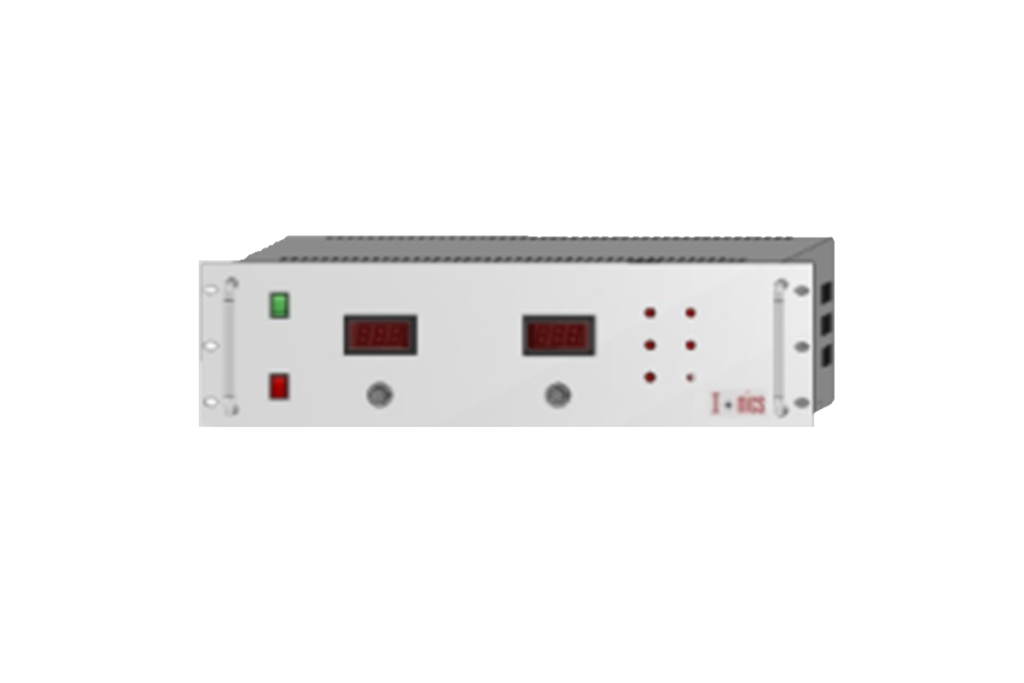
IONICS High Current Power Supply
10A TO 200A, 2.2KW TO 6KW
REGULATED HIGH CURRENT POWER SUPPLY
10A to 100A upto 2kW
This series of power supplies incorporate the high frequency switch mode technology to give precision regulated & highly stable rack mountable units with current range up to 600A catering to a wide variety of scientific and industrial applications.

TECHNICAL SPECIFICATIONS
| PARAMETER | SPECIFICATION |
|---|---|
| Input Voltage | 230V ±10% AC, 50Hz, single phase |
| Output Current Range* | 10A to 100A |
| Output Power Range* | 500W to 2kW |
| Current Sensing* | By highly stable DCCT |
| Polarity | Positive |
| Voltage Regulation Line | ≤ 0.05% for ±10% variation |
| Voltage Regulation Load | ≤ 0.1% for no load to full load variation |
| Current Regulation Line | ≤ 0.05% for ±10% variation |
| Current Regulation Load | ≤ 0.1% for no load to full load variation |
| Ripple | < 0.1% rms at full load |
| Stability | < 0.05%/hour after 1 hour warm up |
| Temperature Coefficient | < 0.05%/ºC |
| Regulating Mode | Constant current – Constant voltage |
| Cooling | Forced air cooling |
| Current & Voltage Control (0 to full rated current / voltage) | Local : By 10-turn potentiometers on the front panel Remote : 0 to 10V DC signals for voltage & current control; OR Control through computer interface* |
| Protections* | Against over current, over voltage, short-circuit and arc |
| Remote Controls & Signals through Pluggable Connector/D-Connector (External RS232 Microcontroller Module)* | 10V DC reference. 10V DC HC enable signal 0 to 10V DC signal for voltage & current control 0 to 10V DC signal for voltage & current monitoring |
| Front Panel | Power ON/OFF switch with indication Output ON/OFF switch with indication 3½ digit LED current and voltage meters (4½ digit available on request) 10-turn potentiometers for current and voltage control Constant current – constant voltage mode indication Fault indications Push button for trip reset |
| Back Panel | Terminal block for 3 phase input Terminal for HC output with bus bars depending on power rating Stud for grounding the unit |
| Topology | PWM-controlled switch mode |
| Switching Device | IGBT |
| Cabinet | 19” rack, powder coated |
*Optional. To be specified by the user.
Remote Interface Connector Configuration
| Pins | 14 Pin Pluggable Connector ( Analog Interface) | 25 Pin D Connector (Digital Interface) |
|---|---|---|
| 1 | Earth | Earth |
| 2 | Common | Common |
| 3 | Interlock | HV Enable |
| 4 | HV Enable | Voltage Control Remote |
| 5 | 10 V DC Reference | Current Control Remote |
| 6 | Common | Over Voltage Control Remote* |
| 7 | Voltage Control Remote | Over Current Control Remote* |
| 8 | Voltage Control Local | Common |
| 9 | Common | Voltage Monitor |
| 10 | Current Control Remote | Current Monitor |
| 11 | Current Control Local | Reserved Monitor* |
| 12 | Common | Reserved Monitor* |
| 13 | Voltage Monitor | Common |
| 14 | Current Monitor | +Mode Status |
| 15 | Interlock Status | |
| 16 | HV ON Status | |
| 17 | Common | |
| 18 | PS Fault Status* | |
| 19 | Over Voltage Status* | |
| 20 | Over Current Status* | |
| 21 | Over Temperature Status* | |
| 22 | Open Circuit Status* | |
| 23 | Phase Failure Status* | |
| 24 | Reserved Status* | |
| 25 | Common |
*Optional. To be specified by the user.
